Vector Network Analyzer Extenders

Description

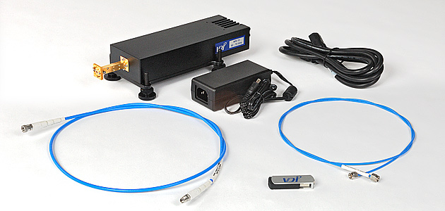
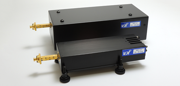
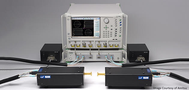
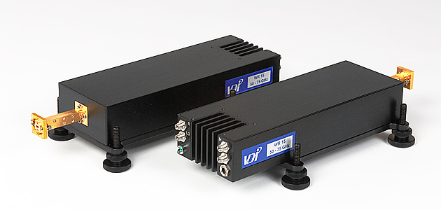
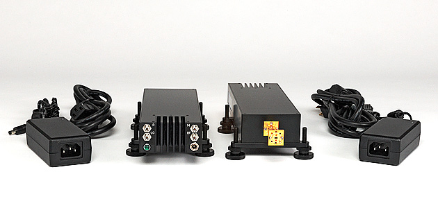
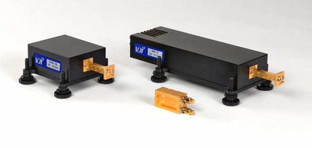
VDI’s VNA Extenders deliver high performance network analyzer frequency extension into the THz range. Models cover 26 GHz to 1,100GHz with additional bands in development. In addition to our full Transceiver (TxRx) modules, VDI also offers Transmit-Reference (TxRef) modules and Receive only (Rx) modules that deliver optimized performance for specific applications. These modules combine high test port power and exceptional dynamic range to deliver industry leading performance. They are compatible with most network analyzers and can be integrated into probe stations and antenna chambers. Power leveling and sweeping is also supported when used with our PM5 Power Meter

Options

– Increased test port power (for selected bands)
– Micrometer driven variable attenuators (~0-30dB)
– Configured from 1.2m to 5m cables (Standard configuration is 1.2m, 5m option)
– Waveguide calibration kits
– Extended dynamic range modules for high loss environments

General Specifications
VNA Extension Modules
WM-380 (WR-1.5) to WM-250 (WR-1.0) Mini and WR-28 to WM-570 (WR-2.2)
 DescriptionSpecificationConnector
RF InputTypical / Damage, -20 Option (Default)10 dBm ± 3 dB / 16 dBm
<20 GHz
2.9mm (f)
Typical / Damage, -20 Option (Default)
with -5m option 
2 dBm ± 3 dB / 8 dBm
<20 GHz
2.9mm (f)
Typical / Damage, -40 Option0 dBm ± 3 dB / 6 dBm
<45 GHz 
2.9mm (f)
LO InputTypical / Damage (Default)10 dBm ± 3 dB / 16 dBm
<20 GHz
2.9mm (f)
Typical / Damage, -5M Option 2 dBm ± 3 dB / 8 dBm
<20 GHz
2.9mm (f)
IF Outputs
(Reference and Measurement)
Maximum, Direct Connection (279 MHz)-9 dBm2.9mm (f)
Maximum, Controller (7.6 MHz)-21 dBm2.9mm (f)
Test PortVDI Precision FlangeSee Flange DiagramUG-387/UM
Power SupplyAC Input100-240VAC, <3.5A,
50-60 Hz
U.S. or E.U.
DC Output9V / 4A2.1mm ID x 5.5mm OD
x 9.5mm (f)
Operating TemperatureTypical / Recommended25°C / 20-30°C
Typical Enclosure DimensionsTxRx & TxRef Modules (in.)
WR28 to WR19
9.5 x 3.0 x 1.5
TxRx & TxRef Modules (in.)
WR15 to WR2.2
8.5 x 3.0 x 1.5
TxRx & TxRef Modules (in.)
WR28 to WR19, -Atten Option
 Contact VDI
TxRx & TxRef Modules (in.)
WR28 to WR19, -Atten Option
8.5 x 3.0 x 1.5
Rx Modules (in.)
[New, Serial Number: VNAX 2400 and higher]
4.75 x 3.0 x 1.5
Rx Modules (in.)
[Old, Serial Number: VNAX 2399 and lower]
3.75 x 3.0 x 1.5 
Typical WeightTxRx & TxRef Modules (lbs.)  4
Rx Modules (lbs.) 2
General Specifications
VNA Extension Modules
VNA Extension Modules (WR1.5 to WR0.65) – Standard Size, Not Mini
 DescriptionSpecificationConnector
RF InputStandard Frequency Input (Typical / Damage)10 dBm ± 3 dB / 16 dBm
<20 GHz
2.9mm (f)
Standard Frequency Input (Typical / Damage)
with -5m option 
2 dBm ± 3 dB / 8 dBm
<20 GHz
2.9mm (f)
High Frequency Input (Typical / Damage)0 dBm ± 3 dB / 6 dBm
<45 GHz 
2.9mm (f)
LO InputTypical / Damage (Default)10 dBm ± 3 dB / 16 dBm
<20 GHz
2.9mm (f)
Typical / Damage, -5M Option 2 dBm ± 3 dB / 8 dBm
<20 GHz
2.9mm (f)
IF Outputs
(Reference and Measurement)
Maximum, Direct Connection (279 MHz)-9 dBm2.9mm (f)
Maximum, Controller (7.6 MHz)-21 dBm2.9mm (f)
Test PortVDI Precision FlangeSee Flange DiagramUG-387/UM
Power SupplyAC Input100-240VAC, <3.5A,
50-60 Hz
U.S. or E.U.
DC OutputSee VDI-175 Datasheet
Operating TemperatureTypical / Recommended25°C / 20-30°C
Typical Enclosure DimensionsTxRx & TxRef Modules (in.)
11 x 5 x 3
Rx Modules (in.)
8 x 5 x 3
Typical WeightTxRx & TxRef Modules (lbs.)  9
Rx Modules (lbs.) 4


PossibleVNAConfigs

Contact vdirfq@vadiodes.com for more information.

 
Vector Network Analyzer (VNA) Extenders – Summary of Specifications
 
Waveguide Band
Frequency Coverage
(GHz)
Dynamic
Range
(BW=10Hz,dB)
  
Test Port Power 
(dBm, typical)
Stability (typical) Test Port Input Limit  (estimate, dBm, damage)
TxRx, TxRef 
 Directivity (dB, typical)
 Standard   Extended‡ Typical
Minimum
Magnitude (±dB)Phase
(±deg)
WR2826-40120110130.1523330
WR1940-60120105170.1523130
WR1550-7547-77120110180.101.53030
WR15 SE Option50-7547-77120110130.101.53030
WR1260-9055-95120110180.101.53030
WR12 SE Option60-9055-90120110 13 0.10 1.5  30  30 
WR1075-11067-115120110180.101.53030
WR10 
SE Option
75-11067-110120110-10.101.52030
WR8.090-140120110 160.1523030
WR6.5110-170120110 130.2543030
WR5.1140-220120110 60.2543030
WR5.1
(EB Option)
140-220130-220120110 60.2543030
WR4.3170-260115110 40.342830
WR3.4220-330115105 10.36 26 30
WM-710
(WR2.8)
260-400110100-10.56 23 30
WM-570
(WR2.2)
330-500325-500110100-3 0.5 6  10 30
WM-380
(WR1.5) Mini
500-750110*95*-120.44730
WM-250
(WR1.0) Mini
750-110095*75*-23 0.5  6 -3 30
WM-164
(WR0.65**)
1100-150060*40*-451 20 -3 30

*The dynamic range specifications assume that low phase sources are used, like those used in the modern Keysight PNA / PNA-X analyzers
with DDS synthesizers. While compatible, other VNAs may reduce dynamic range.

**WM164 (WR0.65) performance is specified for a TxRx-Rx configuration. Performance of a TxRx-TxRx configuration is estimated to have a 
~15 dB degradation of dynamic range and may additionally require the use of a mmWave controller. 

Test Port Input Powers exceeding the peak Test Port Power of the TxRx or TxRef module will compress the module.


General Notes: 

Extension modules are compatible with all modern VNAs. Please consult with VDI to discuss VNA and module configurations that will yield the best performance for your application.

Technical Notes:

1. Test Port Power is typical, reduced power is possible at band edges. 

2. Stability is specified for 1 hour after system warm-up, in stable environment with ideal cables.

3. Specifications assume a through measurement with two TxRx heads.

4. Specifications are measured on a Keysight PNA/PNAX with front panel connection at 25°C typical.

5. The dynamic range (RBW=10Hz) is measured by first connecting two TxRx modules together and normalizing the un-calibrated S21 & S12. The heads are then disconnected and terminated with a waveguide short. The RMS average of 10 sweeps of the measured S21 & S12 gives the system dynamic range.

6. Typical Module Dimensions exclude testport (2″ standard testport for all modules except WM250 (WR1.0), where a 1″ testport is used)

Where noted, Extended Frequency Coverage applies; module performance within the standard band conforms to standard specifications while performance in the extended regions can be degraded as follows:

-The minimum and typical dynamic range is degraded by 10dB or less, compared to the specification for the standard band, with the exception of WR5.1.

-For WR5.1, the minimum dynamic range is 95dB (15dB degradation compared to the standard band specification). 

-The test port power typical across the extended band is degraded by 5 dB or less compared to the specification for the standard band. 

Contact vdirfq@vadiodes.com for more information.


PXI VNAX

VDI offers VNAX module configurations that are compatible with the Keysight PXI or Streamline VNA product lines. For specifications, please refer to page 5 of this Keysight document for the latest specifications. The specifications listed below are accurate as of May 9, 2023. The VNAX-AM (Streamline VNA to VNAX Adapter Module) may be required for some configurations 

   
P50xxA/B Streamline
M980xA PXI VNA
 
P93xxA/B Streamline
M937xA PXI VNA
 
Part Number
Frequency Band (GHz)Test Port  Power 
(dBm typ)


Dynamic
Range
(BW=10Hz,dB)
Dynamic
Range
(BW=10Hz,dB)
 Standard   Extended Typical
Minimum
TypicalMinimum
WR15VNATxRxM*50-7547-77 18  11010010595
WR15VNATxRxM-SE* 50-75  47-77 13 110 100 10595
WR15VNATxRxM-P 50-75 13 1059510595
WR12VNATxRxM*60-9055-95 18  110100 105 95
WR12VNATxRxM-SE*60-9055-9013 110100105 95 
WR12VNATxRxM-P60-9013 105 95 105 95 
WR10VNATxRxM*75-11067-115 18  11010010595
WR10VNATxRxM-SE*75-11067-110 -1  11010010595
WR10VNATxRxM-P  75-110  16 105 95  105  95 
WR10VNATxRxM-P-SE  75-110 -1 10595 105  95 
WR8.0VNATxRxM*  90-140  16 110 100  95 85
WR6.5VNATxRxM* 110-170  13  110 100–   –
WR5.1VNATxRxM* 140-220   6   110 100N/AN/A
WR4.3VNATxRxM* 170-260   4  110100 N/A  N/A 
WR3.4VNATxRxM* 220-330   1  110100N/A N/A 

*VNAX-AM (Streamline VNA to VNAX Adapter Module) is required to operate Standard VDI VNAX Modules with
Keysight Streamline or PXI VNA.


High Power VNAX Configuration

VDI offers VNA Frequency Extension Modules with Higher Test Port Power compared to the standard VNAX modules. The High Power VNAX modules conform to all other standard S-parameter performance specifications. The typical and minimum dynamic range may be slightly reduced. 

    
Product Specifications for VNAX-HP Modules


  Waveguide 
Band
(GHz)
RF
 Frequency 
(GHz) 
Part
Number

 Test
 Port Power 
(typ., est.)

WR-6.5110 – 170  WR6.5VNATxRxM-HP2  17 
WR-4.3170 – 260  WR4.3VNATxRxM-HP4  17 

 Additional high power options and frequency bands are available.

 Contact vdirfq@vadiodes.com for more information. 

Calibration Kits

VDI offers banded waveguide calibration kits for s-parameter calibration of our extension modules. Two different calibration techniques are offered dependent upon the frequency of operation: TRL (Through-Reflect-Line) calibrations for WR28 through WR3.4; SOLT (Short-Open-Load-Through) calibrations for WR2.8 through WR1.0. VDI only manufactures Type B versions of the calibration standards to support both QW (Quarter Wave Delay Shim) and QD (Quarter Wave Delay Short) standards. These standard versions are described here. Information about Type A calibration standards are included in the VNAX Manual. Electronic calibration kit definitions are available for download below. 

cal kit 1
cal kit 2
cal kit 3
Downloads  

Use the image below to identify the correct type of calibration kit needed.

calkitimageRev

    Type A Calibration Kits have been discontinued but Type A Calibration Kit Definitions may
    still be downloaded here.

    Questions? Contact VDI at
 info@vadiodes.com

Dual Source Module Option

The Dual Source (DS) option for VDI VNAX modules adds a second source module and a directional coupler into the standard TxRx Module (see block diagram below). This enables two-tone measurements to allow users to characterize device linearity. VNAX-DS modules have slightly reduced test port power and dynamic range compared to standard VNAX modules. VNAX-DS modules conform to all other standard
S-parameter performance specifications. Specifications listed below are specific for the DS option. For setup instructions or other information about our VNAX-DS Modules, please Contact VDI. For more information on VDI VNAX Modules, please refer to VDI-707.1 (VNAX Product Manual) located under the Resources tab.

The 3DB Option includes a 3dB combining coupler instead of a 6dB combining coupler. With the 3DB option, the Test Port Power imbalance between Source 1 and Source 2 is reduced while sacrificing maximum test port power compared to the standard configuration. 
 

    VNAX-DS Dual Source Specifications
Waveguide Band
(GHz)
 
Frequency Band
(GHz)
 
Dynamic Range
(BW=10Hz,dB)
Test Port Power
(dBm, typ.)
 
Standard ExtendedTypical Minimum  Source 1  Source 2 
WR15 50-75 47-77  115  105  14 (est.)  9 (est.) 
WR15 (-3DB) 115  105   13   13  
WR12 60-90 55-95    115    105   14  9 
WR12 (-3DB)  115   105 1313
WR10 75-110 67-115    115   105   13  7
WR10 (-3DB) 115  105  13 13 
WR8.0 90-140  110  100 127
WR8.0 (-3DB) 110  100  10 (est.) 10 (est.) 
WR6.5 110-170 110 100 12 (est.)7 (est.)
WR6.5 (-3DB)110 100  10 (est.) 10 (est.) 
WR5.1 140-220 110 100 3 (est.)-2 (est.)
WR5.1 (-3DB)1101001 (est.)1 (est.)

Where noted, Extended Frequency Coverage applies; module performance within the standard band conforms
to standard specifications while performance in the extended regions can be degraded as follows:

-The minimum and typical dynamic range is degraded by 10dB or less, compared to the specification for the
standard band.

-The test port power typical across the extended band is degraded by 5dB or less compared to the specification
for the standard band.


DualsourceimageREV2


Dual RX Option

DualRXimage1


For VDI Mini Rx Modules, VDI offers a Dual Rx configuration. The Dual Rx Module integrates two Rx chains in the same enclosure, with 1.375” center-to-center spacing between the test ports. Each Rx chain meets the standard specifications for Rx modules.


VDI Dual Rx Specifications

Description

WR19  

 WR15 

WR12 
 

WR10

WR8.0

WR6.5
 

 WR5.1  

RF Frequency Band (GHz)40-6050-7560-9075-11090-140110-170140-220
Test Port Input Power Limits
(Compression/ Damage, High Sensitivity Operation)
-10 / 0-10 / 0-10 / 0-10 / 0-10 / 0-10 / 0-10 / 0
LO Harmonic Factor4666121212
LO Input Power (typical, +/-3 dB)2222222
Description WR4.3WR3.4WM710
(WR2.8)
WM570
(WR2.2)
WM380
(WR1.5)
WM250
(WR1.0)
 
RF Frequency Band (GHz)170-260 220-330 260-400 330-500 500-750 750-1,100 
Test Port Input Power Limits
(Compression/ Damage, High Sensitivity Operation)
-10 / 0-10 / 0-10 / 0-20 / 0-10 / 0-20 / -10 
LO Harmonic Factor 2424 24 36 54 72  
LO Input Power (typical, +/-3 dB) 2 
 

Dual Source Mech Drawing

  Contact VDI for additional information and details.

Product Manuals and Specifications


WM-164 (WR-0.65) Standard Size Drawings  
TxRx and TxRef with footplate:  .pdf  .stp

Rx:  .pdf  .stp

 
WR-15 to WM-250 (WR-1.0) VNAX Module Drawings
TxRx with Internal Attenuator Option and footplate:  .pdf  .stp
TxRx with Internal Attenuator Option without footplate:  .pdf  .stp
TxRx and TxRef with footplate:  .pdf.stp 
TxRx and TxRef without footplate:  .pdf  .stp
TxRx and TxRef with footplate (WR1.0 Only):  .pdf  .stp
TxRx and TxRef without footplate (WR1.0 Only):  .pdf  .stp
Rx with footplate (Serial Number: VNAX 2400 and higher):  .pdf  .stp
Rx without footplate (Serial Number: VNAX 2400 and higher):  .pdf  .stp
Rx with footplate (WR1.0 Only):  .pdf  .stp
Rx without footplate (WR1.0 Only):  .pdf  .stp 
 
WR28 to WR19 Drawings 
TxRx with Internal Attenuator  (Contact VDI)
TxRx and TxRef with footplate:  .pdf  .stp 
TxRx and TxRef without footplate:  .pdf  .stp
WR19 Rx Standard Operation Mode with footplate:  .pdf  .stp 
WR19 Rx Standard Operation Mode without footplate:  .pdf  .stp  
WR19 Rx High Sensitivity Mode with footplate:  .pdf  .stp 
WR19 Rx High Sensitivity Mode without footplate:  .pdf  .stp  
WR28 Rx Standard Operation Mode with footplate:  .pdf  .stp
WR28 Rx Standard Operation Mode without footplate:  .pdf  .stp  
WR28 Rx High Sensitivity Mode with footplate:  .pdf  .stp 
WR28 Rx High Sensitivity Mode without footplate:  .pdf  .stp  
  
WR15 to WR10 Dual Source Module Drawings 
With footplate:  pdf .stp
Without footplate:  .pdf  .stp
   
 
Scroll to Top